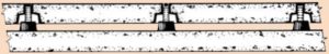
TYPICAL FLOOR WITHOUT MACHINERY
LDS JACK-UP SYSTEM FOR TV Studios, Theatres, Bowling Alleys, Kitchens, Squash Courts, Exercise Rooms, etc.
1.01 Description
We have left the blank below for you to fill in the name of the area, i.e. Auditorium, TV Studio, etc. Please specify floor finish such as hardwood or tile as you normally do in another section.
- Scope of Work
- Isolate floating floors from building structure by means of jack-up LDS isolators and perimeter isolation in each of the (fill in name of area) _____________________.
If sound barrier walls are used, add the following: - Build sound barrier walls on the floating floors.
- Isolate floating floors from building structure by means of jack-up LDS isolators and perimeter isolation in each of the (fill in name of area) _____________________.
- Substitution of Materials
- Substitute materials shall meet or exceed the “quality” of the products which are listed in these Specifications. Submit samples and test reports by an independent laboratory for consideration on this project.
1.02 Design
- Intent
- The floating floor system shall consist of a 4”(100mm) thick concrete slab isolated from and supported 2”(50mm) above the structural slab by resilient LDS isolators within cast iron housings designed to jack up the floor after pouring on the sub-floor. Sub floors shall be waterproofed under kitchens.
If sound barrier walls are used, add the following:
Sound barrier walls consisting of 6”(150mm) filled concrete block (Barrier wall construction can be changed when writing specification) shall rest on the floating floor with a 31/2”(90mm) air gap to the structural walls. (31/2”(90mm) may be reduced to 2”(50mm) if no sway braces are needed.) - The floating floor slab shall be isolated from adjoining walls, columns and curbs by means of perimeter isolation.
- Any floor drains, piping, conduit and duct penetrations must not short circuit the isolation system.
- In seismic zones the floating floor shall be restrained horizontally by curbs or walls designed to withstand the horizontal seismic forces. Solid bridge bearing LDS pads shall be interspersed between perimeter isolation to withstand the seismic forces with a maximum deflection of 0.2”(5mm). When perimeter cannot be used for seismic constraint, intersperse horizontal restraints within floor system.
- The floating floor system shall consist of a 4”(100mm) thick concrete slab isolated from and supported 2”(50mm) above the structural slab by resilient LDS isolators within cast iron housings designed to jack up the floor after pouring on the sub-floor. Sub floors shall be waterproofed under kitchens.
- Performance Requirements
- The floating floor system shall have a minimum rating of STC-79 and INR+17 as verified by an independent laboratory in prior tests.
- Floor System Construction Procedure
- The setting of all isolation materials and raising of the floor shall be performed by or under the supervision of the isolation manufacturer.
- Set and waterproof any drains and lower pipe seals in keeping with waterproofing specifications.
- Cement perimeter isolation around all walls, columns, curbs, etc.
- In seismic zones intersperse the perimeter isolation with bridge bearing quality LDS pads the thickness of the perimeter isolation.
- Cover entire floor area with 6 mil (0.15mm) plastic sheeting and carry sheeting up perimeter isolation.
- Place bell-shaped castings on maximum 54”(1370mm) centers in the general areas in strict accordance with the approved drawings prepared by the isolation manufacturer. Additional reinforcement must be detailed on isolation manufacturer’s drawings when required.
If sound barrier walls are used, add the following:
Perimeter isolators shall be selected to support the wall weight in addition to the perimeter of the floating floor. - Place reinforcing as shown on the drawings and pour floor monolithically.
- Raise floor 2”(50mm) by means of the jack-screws.
- Caulk perimeter isolation in all locations and grout jack-screw holes.
If sound barrier walls are used, add the following: - Construct block walls on the floating floor being careful that mortar does not drop behind the walls. Place 2”(50mm) fiberglass bats against the structural wall as a precaution. Provide sway braces and isolated angle iron wall braces at the top of the walls. Caulk angle iron braces.
- Submittals
- Detailed product drawings and Load/Deflection curves of all isolators.
- AASHTO Test Reports on all properties in table 2.01 A from an accredited independent laboratory for all rubber durometers used.
- Dynamic stiffness test from an accredited independent laboratory at 5, 10 and 15 Hz, showing dynamic stiffness does not exceed 1.4.
- Isolation frequency not to exceed 9 Hz at stated deflection.
- Acoustical test data from an independent laboratory showing a minimum STC of 79 and a minimum INR of 17 using a 4”(100mm) concrete floating floor, a 6”(150mm) structural floor and a 2”(50mm) air gap.
- A drawing or drawings showing:
- Dead, live and concentrated loads.
- Isolator sizes, deflections, frequencies and locations.
If sound barrier walls are used, add:
wall sway brace and isolated angle iron brace sizes, locations and frequencies. - Any drain and penetration locations.
- Size, type, elevation and spacing of concrete reinforcement.
- Caulking details.
- Floating floor and wall construction procedure.
1.03 Quality Assurance
- Floating floor system components shall be designed and fabricated by a manufacturer with at least ten years experience in one hundred similar installations.
- The floating floor isolation materials shall be installed and the floor raised by or under the supervision of the isolator manufacturer.
1.04 Site Conditions
- If site conditions are unsatisfactory or raise questions about the installation of the floating floor, the work will not proceed until the condition has been corrected in a manner acceptable to the isolation manufacturer. The sub-floor must have the same pitch as the top of the floating floor or special provisions made for isolator housings of different height.
1.05 Sequencing and Scheduling
Coordinate work with other trades and coordinate scheduling with the construction supervisor to minimize delays.
2.01 Isolators
- Bell shaped castings with integral lugs to locate reinforcing, shrouding 2”(50mm) thick LDS isolators molded to the following AASHTO bridge bearing specifications. All housings shall have 3/4”(20mm) minimum diameter jackscrews. Deflections shall not exceed 0.3”(7.5mm) nor the frequency 10Hz. Isolators shall be Mason Industries type FSN.
AASHTO Bridge Bearing Specifications for Polyisoprene ORIGINAL PHYSICAL PROPERTIES TESTED FOR AGING COMPRESSION SET ASTM D-395 22hrs/158°F Method B LONG TERM CREEP ISO8013 168 hrs Tests: Tests: ASTM D-2240 & D-412 OVEN AGING(70hrs/158°F)
ASTM D-573OZONE
ASTM D-1149ASTM D-395 ISO8013 Durometer Shore A Tensile Strength (min) Elongat. at Break (min) Hardness (max) Tensile Strength (max) Elongat. at Break (max) 25 pphm in air by Vol. 20% Strain 100°F 22hrs/158°F Method B 168 hrs 40±5 2000 psi 500% +10% -25% -25% No Cracks 25%(max) 5%(max) 50±5 2250 psi 450% +10% -25% -25% No Cracks 25%(max) 5%(max) 60±5 2250 psi 400% +10% -25% -25% No Cracks 25%(max) 5%(max) 70±5 2250 psi 300% +10% -25% -25% No Cracks 25%(max) 5%(max) NOTE: 40 Durometer is not included in AASHTO Specifications. Numbers are Mason standar
If sound barrier walls are used, add the following:
- Wall Sway Braces: Double acting LDS sway braces with a fail safe feature in three planes. Braces shall be furnished with a bracket for bolting to the structural wall and a hooked end for insertion in the masonry joint. Braces shall have a frequency not in excess of 10Hz based on the weight of the wall area per brace and a vertical stiffness not in excess of 50% of the horizontal. Sway braces shall be Mason Industries Type DNSB.
- Angle Brackets: 11/2”(40mm) x 2”(50mm) angle iron sections with provision for bolting to the structure and a minimum thickness of 3/8”(9mm) sponge cemented to the vertical leg. Angle Brackets shall be Mason Industries AB-716.
2.02 Bond Breaker Material
- Provide one (1) layer of 6 mil (0.15mm) polyethylene sheeting.
2.03 Perimeter Isolation
- Minimum 3/4”(20mm) thick PVC foam, density 7 lbs/ft3 average. PVC foam shall be Mason Industries P7.
- In seismic zone perimeter isolation shall be interspersed with 3/4”(20mm) thick, 60 durometer LDS bridge bearing pads the height of the perimeter material. Bridge bearing pad shall be made to the same AASHTO specifications, as shown for the FSN mountings and sized for a maximum deflection of 0.2”(5mm) at maximum earthquake forces. Interspersed pads shall be Mason Industries Type LDS-BBP.
2.04 Perimeter Caulking Compound
- Non-hardening, drying or bleeding. Troweling or pouring grade. Caulking compound shall be Mason Industries Type CC-75.
2.05 Floating Floor Drains
- Cast iron design. The upper funnel section cast into the floating floor. Lower bucket, built into the structure, shall retain water surrounding the upper section as a between floors sound seal. Weep holes are required to drain the structural floor. Floor drains shall have water proofing membrane clamps. Floor drains shall be Mason Industries Type CFD-18591.
3.01 Installation
Install the floating floor systems according to the installation and adjustment procedures and drawings submitted by the isolator manufacturer and approved by the architect.