ISOLATED CEILINGS SUSPENDED BY RESILIENT HANGERS
- Scope
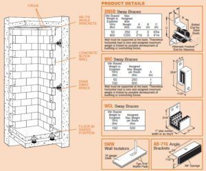
- Isolate masonry walls shown on drawings from building structure by supporting them on the floating concrete floor. Brace them with resilient sway braces and anchor the top by means of resiliently lined angle iron guides.
- Materials
- Wall Sway Braces: Double acting LDS sway braces with a fail safe feature in three planes. Braces shall be furnished with a bracket for bolting to the structural wall and a hooked end for insertion in the masonry joint. Braces shall have a frequency not in excess of 10Hz based on the weight of the wall area per brace and a vertical stiffness not in excess of 50% of the horizontal.
- Angle Brackets: 11/2”(40mm) x 2”(50mm) angle iron sections with provision for bolting to the structure and a minimum thickness of 3/8”(10mm) sponge cemented to the vertical leg.
- Caulking Compound: Non-hardening, non-drying and non- bleeding.
- Wall System Construction Procedure
- If the drawings call for sway braces, raise the floating floor to operating position before attaching the first row of sway braces to the walls. If no sway braces are used, construct the walls before raising floor if walls do not cover isolator access.
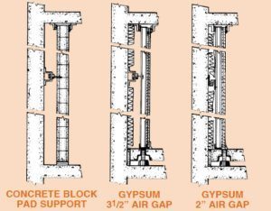
- Build concrete block wall on perimeter of floating floor leaving a 31/2”(90mm) gap between the building wall and the floating wall. (31/2”(90mm) may be reduced to 2”(50mm) if no sway braces are needed.)
- Cement 2”(50mm) fiberglas to the structural wall. When buttering all joints, concrete should not be allowed to drop behind the wall and short circuit the air gap. The fiberglas will prevent accidental droppings.
- Set sway braces as shown on drawings and anchor hooks in mortar joints.
- Bolt one angle bracket to structural ceiling with sponge leg facing new wall.
- Continue construction to ceiling leaving a minimum gap of 1/2”(12mm) on top with the floating floor elevated. Check to be certain gap is continuous.
- Secure other angle to structural ceiling with sponge leg vertical and bearing on wall. Angles shall be continuous on both sides of wall.
- Caulk all accessible joints.
- Submittals
- Load and deflection curves of all sway braces in both planes.
- Detailed drawings of angle braces.
- Manufacturer
- Subject to compliance with the specifications, the following products are approved for use: Type DNSB Sway Braces,
AB-716 Angle
Braces and CC-75 Caulking Compound all as manufactured by Mason Industries, Inc.
- Subject to compliance with the specifications, the following products are approved for use: Type DNSB Sway Braces,
The method below is used when walls are extremely tall and heavy so that support on the floating floor becomes impractical. There are also installations where only adjacent space must be protected and no floating floor is required.
MASONRY WALL ISOLATION, WALLS RESTING ON ISOLATION PADS.
- Scope
- Isolate masonry walls shown on drawings from building structure by supporting them on two 5/8”(16mm) thick LDS isolation pads, bracing them with resilient sway braces and anchoring the top by means of resiliently lined angle iron guides.
- Materials
- Wall Isolation Pads: Two layers of 5/16”(8mm) thick LDS waffle pad molded to the following AASHTO Table 1 properties and cemented to a 16 gauge sheet metal form cut to the full width of the wall. Sections shall be furnished 6’(2m) long with corrugated steel anchors riveted or welded to the plates to facilitate anchoring of the walls. Waffle pad may be cut in lengthwise strips to reduce area and allow for the proper deflection. Dynamic frequency shall not exceed 14Hz.
AASHTO Bridge Bearing Specifications for Polyisoprene ORIGINAL PHYSICAL PROPERTIES TESTED FOR AGING COMPRESSION SET ASTM D-395 22hrs/158°F Method B LONG TERM CREEP ISO8013 168 hrs Tests: Tests: ASTM D-2240 & D-412 OVEN AGING(70hrs/158°F)
ASTM D-573OZONE
ASTM D-1149ASTM D-395 ISO8013 Durometer Shore A Tensile Strength (min) Elongat. at Break (min) Hardness (max) Tensile Strength (max) Elongat. at Break (max) 25 pphm in air by Vol. 20% Strain 100°F 22hrs/158°F Method B 168 hrs 40±5 2000 psi 500% +10% -25% -25% No Cracks 25%(max) 5%(max) 50±5 2250 psi 450% +10% -25% -25% No Cracks 25%(max) 5%(max) 60±5 2250 psi 400% +10% -25% -25% No Cracks 25%(max) 5%(max) 70±5 2250 psi 300% +10% -25% -25% No Cracks 25%(max) 5%(max) NOTE: 40 Durometer is not included in AASHTO Specifications. Numbers are Mason standar
- LDS Cement
- Wall Sway Braces: Double acting LDS sway braces with a fail safe feature in three planes. Braces shall be furnished with a bracket for bolting to the structural wall and a hooked end for insertion in the masonry joint. Braces shall have a frequency not in excess of 10Hz based on the weight of the wall area per brace and a vertical stiffness not in excess of 50% of the horizontal.
- Angle brackets: 11/2”(40mm) x 2”(50mm) angle iron sections with provision for bolting to the structure and a minimum thickness of 3/8”(10mm) sponge cemented to the vertical leg.
- Caulking Compound: Non-hardening, non-drying and non- bleeding.
- Wall Isolation Pads: Two layers of 5/16”(8mm) thick LDS waffle pad molded to the following AASHTO Table 1 properties and cemented to a 16 gauge sheet metal form cut to the full width of the wall. Sections shall be furnished 6’(2m) long with corrugated steel anchors riveted or welded to the plates to facilitate anchoring of the walls. Waffle pad may be cut in lengthwise strips to reduce area and allow for the proper deflection. Dynamic frequency shall not exceed 14Hz.
- Wall System Construction Procedure
- Strike lines on the floors and cement the 6’(2m) long wall supports in position with LDS cement.
- Cement 2”(50mm) fiberglas to the structural wall.
- Lay the first course of blocks being certain to bend up the corrugated anchors to embed them in the mortar joints.
- Build up the concrete wall taking special care to completely butter all joints. Where sway braces are used, leave a 31/2”(90mm) gap between the acoustical wall and the building structure. Do not allow mortar to drop behind wall and short circuit the air gap. The 2”(50mm) fiberglas will help prevent short circuiting.
- Set sway braces as shown on drawings and anchor hooks in mortar joints.
- Bolt one angle bracket to structural ceiling with sponge leg facing new wall.
- Continue construction to ceiling leaving a minimum gap of 1/2”(12mm) on top. Check to be certain gap is continuous.
- Secure other angle to structural ceiling with sponge leg vertical and bearing on wall. Angle shall be continuous on both sides of wall.
- Caulk all joints.
- Submittals
- Load and deflection curves of all sway braces in both planes. Load and deflection curves of wall isolation pads. Detail drawings of angle braces.
- Manufacturer
- Subject to compliance with the specifications, the following products are approved for use: Type SWW Wall Isolators, DNSB Sway Braces, AB-716 Angle Braces and CC-75 Caulking Compound. All as manufactured by Mason Industries, Inc.
NOTE TO ARCHITECT:
When you cannot leave a 31/2”(90mm) gap between the isolated wall and the basic structure, it is necessary to use a stiffer type of sway brace as the LDS materials must be made thinner. If there is an inch and a half gap, the item can be defined as a “Double acting LDS sway brace consisting of two interlocking metal sections separated by 5/16”(8mm) thick LDS waffle pad with a horizontal frequency not exceeding 15Hz based on the total weight of the wall area per brace”. Under materials and manufacturer they should be referred to as type WIC rather than DNSB.

GYPSUM BOARD FLOATING WALLS RESTING ON FLOATING FLOORS
The following specification is meant as a general guide for the construction of gypsum board or similar sound barrier walls. There are so many variations in construction that our specifications can only be very broad and must be specifically tailored to each individual application.
- Scope
- Isolation of gypsum board walls from building structure by putting them on the floating concrete floor, bracing them with resilient sway braces and establishing a sound seal either at the structural or acoustical ceiling.
- Isolation Materials
- Wall Sway Braces: Double acting LDS sway braces with a fail safe feature in three planes. Sway braces shall be made with a bracket for bolting to the building structure and a projecting anchor bolt with adjusting nuts for plumbing the wall structure. Sway braces shall have a horizontal frequency not in excess of 10Hz based on the weight of the wall area per brace and a vertical stiffness not in excess of 50% of the horizontal.
- Angle Brackets: 11/2”(40mm) x 2”(50mm) angle iron sections with provisions for bolting to the structure and a minimum thickness of 3/8”(10mm) sponge cemented to the vertical leg.
- Caulking Compound: Non-hardening, non-drying and non-bleeding.
- One and a half to three pound density fiberglass 2”(50mm) thick.
- Wall System Construction Procedure
- Raise the floating floor to operating position before constructing walls. Bolt the wall foot channel to the perimeter of the floating floor and set the vertical channels in position.
- Bolt the sway braces to the structural wall as shown on the drawing and use the leveling nuts to plumb the channels and set them in their vertical position.
- Attach 2”(50mm) fiberglas to building walls.
- Add horizontal steel members in the normal manner and cover entirety with two layers of 3/4”(20mm) gypsum board staggering and overlapping all seams.
- Where drawings indicate, gypsum board terminates at the structural ceiling, stop the gypsum board 1/2”(12mm) short of the ceiling and lock in place with the 11/2”(40mm) x 2”(50mm) isolation angles on either side with the sponge rubber facing the gypsum board.
- Where the gypsum board forms a seal with the isolation ceiling, terminate the gypsum board as shown on the details without the angle iron braces.
- Caulk all joints.
- Submittals
- Submittals shall include load and deflection curves of all sway braces.
- Manufacturers
- Subject to compliance with the specifications the following products are approved for use: Type DNSB Sway Braces as manufactured by Mason Industries, Inc.
